


JW JW
Category
ProductivityTag
Android app | JW_cad Viewer | CAD file viewing | Dimension measurement | Layer management
Rate
0.00
★★★★★
Reviews
500 +
Installs
50k +
Developer
junkbulk
Content Rating
Everyone
JW_cad Viewer is an application for viewing JW_CAD file and DXF file.
 0.00
0.00 Advertisements
Advertisements
Author's Review
appspicked Review
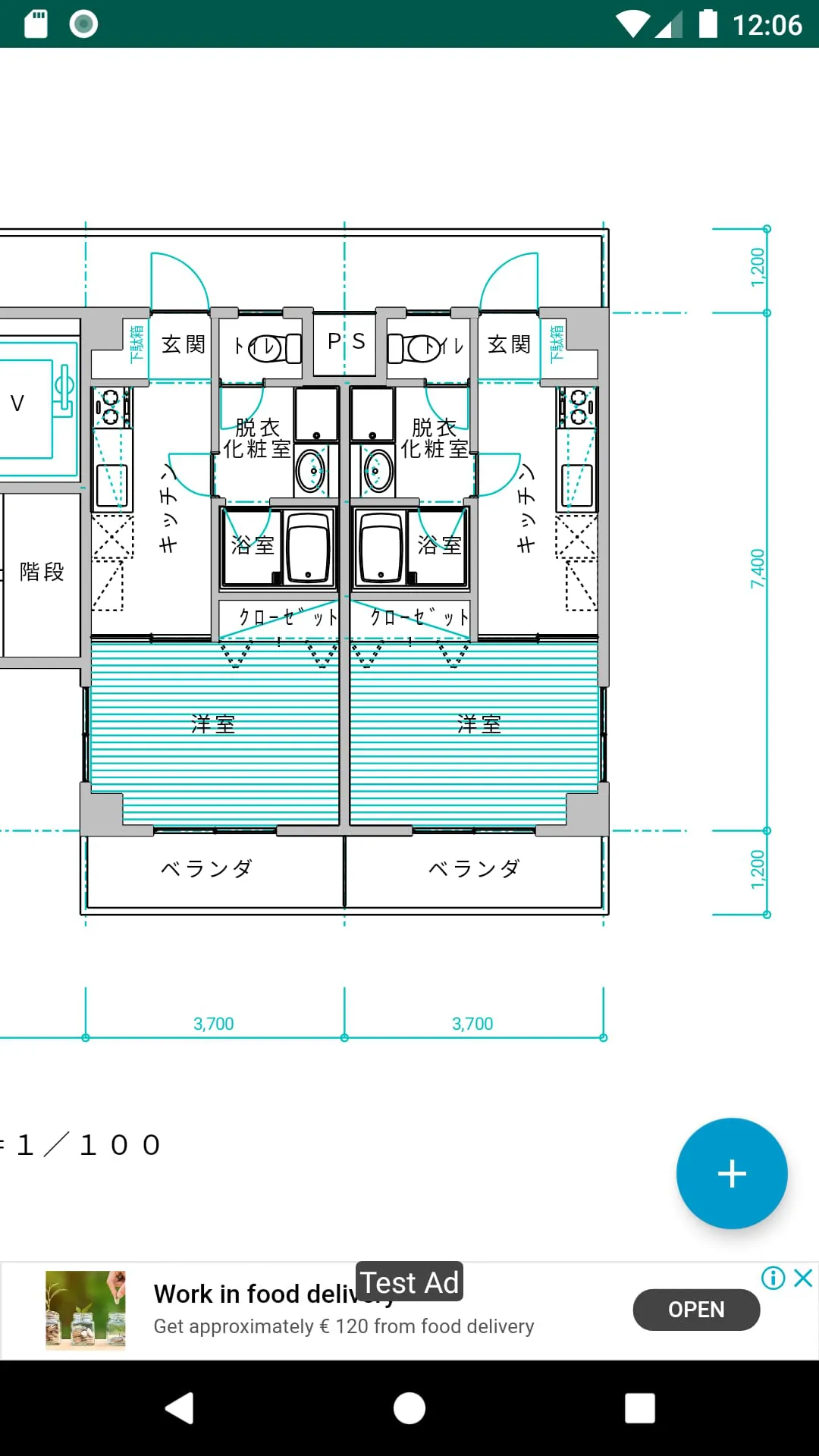
JW_cad Viewer is an application designed for viewing JW_cad files, a popular CAD software format widely used in Japan. This mobile application enables users to open and inspect JW_cad files, including JWW and JWC formats, as well as DXF files, directly on their Android smartphones and tablets. This functionality provides considerable convenience for professionals and hobbyists who need to access CAD drawings while away from their workstations. The application focuses primarily on providing viewing capabilities rather than editing or modification features. Key features include a dimension measurement tool that allows users to measure distances between two points on the drawing, providing horizontal, vertical, and diagonal measurements. This is particularly useful for verifying dimensions or obtaining quick measurements without needing access to the full JW_cad software on a computer. Another significant feature is the ability to control the visibility of layers, enabling users to selectively display or hide different layers within the CAD drawing. This is crucial for managing complex drawings with numerous layers, allowing users to focus on specific aspects of the design. The application supports opening files directly from file managers, although compatibility may vary depending on the specific file manager used. This integration streamlines the process of accessing and viewing CAD files stored on the device or in cloud storage services accessible through the file manager. The user interface is designed to be intuitive, with a prominent '+' button in the lower right corner providing access to various functions. Tapping this button reveals options such as file loading, layer settings, and dimension measurement tools. Loading a file involves selecting the desired JWW, JWC, or DXF file from a file selection dialog. The layer settings button allows users to toggle the visibility of individual layers or layer groups, providing granular control over what is displayed. The dimension measurement tool allows users to specify two points on the drawing, and the application calculates and displays the horizontal, vertical, and diagonal distances between these points. To aid in precise measurement, the application offers a snapping function that automatically snaps the measurement points to lines or endpoints. This feature can be toggled on or off, and users can select the types of snap targets, such as points, centers, or lines. When snapping is enabled, the cursor changes color to indicate that a snap point has been found. The application also includes settings for customizing various aspects of the viewing experience. One important setting is the ability to specify the encoding for DXF files, which is necessary to ensure that text is displayed correctly. Users can choose from encodings such as Shift JIS, ISO_8859_1, and UTF-8, depending on the encoding used when the DXF file was created. The application has certain limitations. It does not support absolute paths for images, meaning that images embedded in the CAD drawing must be located in a specific relative path to be displayed correctly. Text formatting, such as font names and styles, are not rendered in the application, and random line types are not supported. When opening files over a network through a file manager, only images that are included directly within the file can be opened; external references may not be supported. The application is provided free of charge and includes advertising. The developers disclaim any responsibility for damages or losses resulting from the use of the application and do not provide any guarantees of support or maintenance. It is important to note that JW_cad Viewer is not an official JW_cad product but rather an independently developed application based on publicly available information. This is an important disclaimer, emphasizing that the application is not endorsed or supported by the original developers of JW_cad.
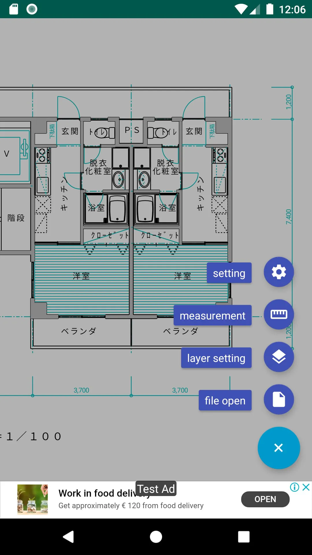
The dimension measurement functionality in JW_cad Viewer is a key feature that significantly enhances its usability for professionals and hobbyists alike. This tool allows users to accurately measure distances between any two points within a CAD drawing directly on their Android devices. This eliminates the need to transfer files to a computer or use dedicated CAD software for simple measurement tasks. The implementation of the dimension measurement tool is designed to be user-friendly and intuitive. When the user activates the dimension measurement mode, the application presents a cursor that can be moved around the drawing. The user then taps on the screen to select the first point for measurement. After the first point is selected, the user moves the cursor to the second point and taps again. The application then calculates and displays the horizontal, vertical, and diagonal distances between the two selected points. This immediate display of all three distance values provides a comprehensive understanding of the spatial relationship between the points. To further enhance the accuracy and ease of use of the dimension measurement tool, JW_cad Viewer incorporates a snapping functionality. This feature automatically snaps the cursor to nearby lines, endpoints, and other significant features within the drawing. This ensures that the measurements are precise and eliminates the need for the user to manually position the cursor with pixel-perfect accuracy. The snapping feature can be toggled on or off, allowing users to choose whether they want the assistance of automatic snapping or prefer to manually select the measurement points. The user can also configure the types of objects that the cursor will snap to, such as endpoints, midpoints, centers, or intersections. This level of customization allows users to tailor the snapping behavior to their specific needs and the characteristics of the drawing they are working with. When the snapping feature is active, the cursor changes color to visually indicate that it has snapped to an object. This provides clear feedback to the user and ensures that they are aware of when the cursor is accurately aligned with a feature in the drawing. However, it is important to note that the intersection snapping feature can be computationally intensive, especially in complex drawings with a large number of objects. In such cases, the application may experience some performance slowdown. The application does not support intersection snapping for block figures, which can be a limitation when working with drawings that make extensive use of block figures. Despite these limitations, the dimension measurement tool in JW_cad Viewer is a valuable asset for anyone who needs to quickly and accurately measure distances within CAD drawings on their Android devices. The combination of intuitive controls, accurate measurement capabilities, and helpful snapping features makes it a convenient and efficient tool for a variety of tasks. From verifying dimensions to obtaining quick measurements for on-site work, the dimension measurement tool in JW_cad Viewer provides a practical solution for accessing and analyzing CAD data on the go.
JW_cad Viewer also provides layer management features, allowing users to control the visibility of different layers and layer groups within a CAD drawing. This is a critical function for handling complex drawings with multiple layers, each representing different aspects of the design. By selectively displaying or hiding layers, users can focus on specific areas of interest, simplify the visual representation, and improve overall clarity. The layer management interface is accessed through the layer settings button, which is typically located within the application's main toolbar or menu. When the user taps the layer settings button, a dialog box or panel appears, displaying a list of all the layers and layer groups present in the CAD drawing. Each layer or layer group is typically represented by a checkbox or toggle switch, allowing the user to easily enable or disable its visibility. The layer management features in JW_cad Viewer are designed to be intuitive and user-friendly. The layer list is typically organized in a hierarchical structure, with layer groups at the top level and individual layers nested underneath. This makes it easy to manage layers that are logically grouped together, such as layers representing architectural elements, mechanical components, or electrical wiring. The user can expand or collapse layer groups to view or hide the individual layers within them. By selectively enabling or disabling layers, users can create customized views of the CAD drawing that highlight specific aspects of the design. For example, an architect might choose to display only the architectural layers, hiding the mechanical and electrical layers to focus on the building's structure and layout. A mechanical engineer, on the other hand, might choose to display only the mechanical layers, hiding the architectural and electrical layers to focus on the machinery and equipment. The ability to control layer visibility is also useful for troubleshooting and problem-solving. By hiding layers that are not relevant to the current task, users can reduce visual clutter and make it easier to identify potential issues. For example, if a user is experiencing problems with the electrical wiring in a building, they can hide all the other layers and focus solely on the electrical layers to trace the wiring and identify any faults. The layer management features in JW_cad Viewer also allow users to save and load layer visibility settings. This is useful for creating predefined views of the CAD drawing that can be quickly accessed and applied. For example, a user might create a view that shows only the architectural layers and save it as Architectural View. They could then create another view that shows only the mechanical layers and save it as Mechanical View. By saving and loading layer visibility settings, users can easily switch between different views of the CAD drawing without having to manually enable or disable layers each time. Overall, the layer management features in JW_cad Viewer provide a powerful and flexible way to control the visibility of layers in a CAD drawing. This functionality is essential for handling complex drawings and allows users to focus on specific areas of interest, simplify the visual representation, and improve overall clarity.
Advertisements
Advertisements
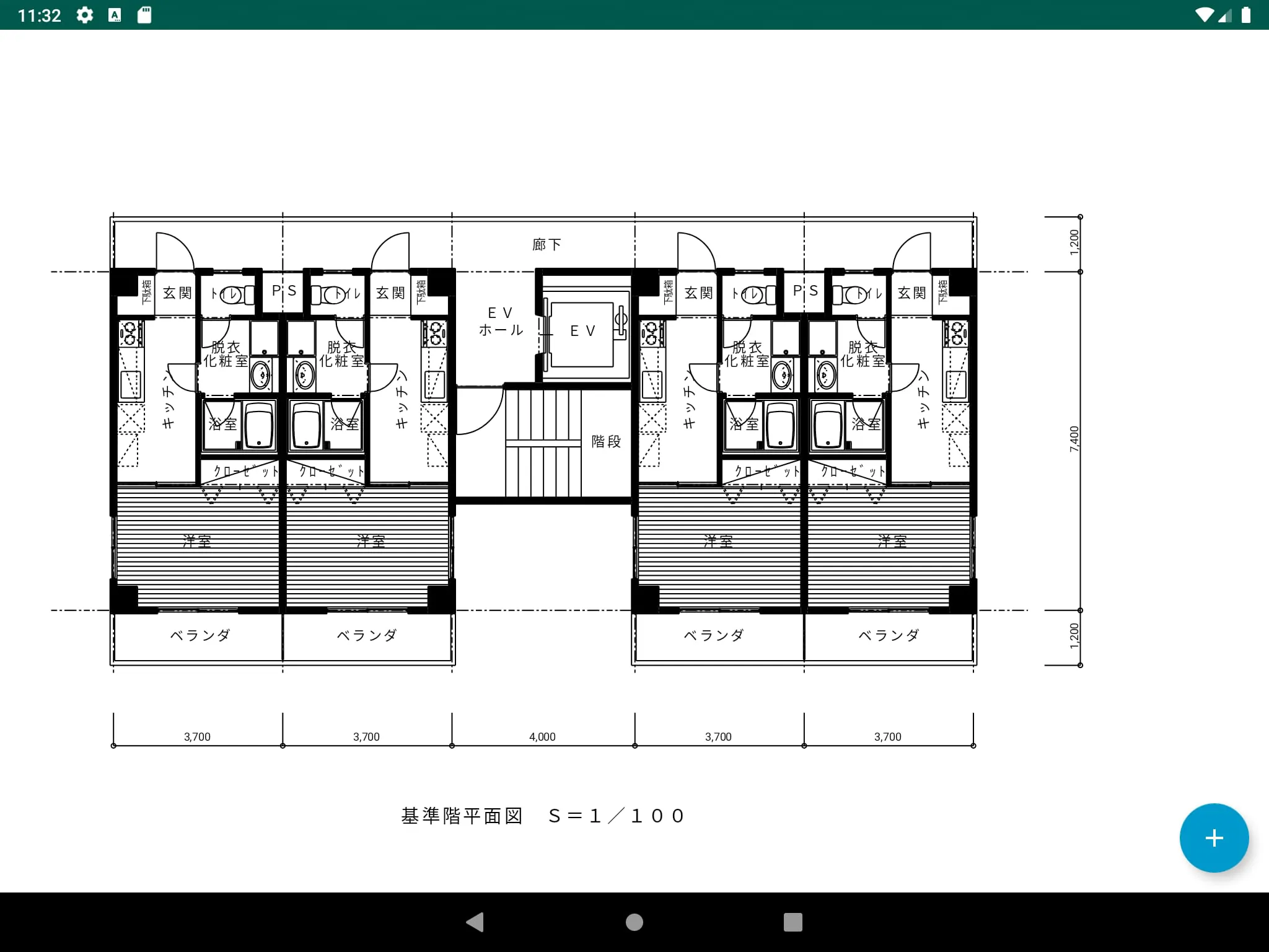
Screenshots
 Download
 Additional Information
Category
ProductivityVersion
Unknown
Tag
Android app | JW_cad Viewer | CAD file viewing | Dimension measurement | Layer management
Rate
0.00
★★★★★
Reviews
500 +
Installs
50k +
Developer
junkbulk
Content Rating
Everyone
JW_cad Viewer is an application for viewing JW_CAD file and DXF file.
Previous Versions
ZIP files require a Split APKs Installer (e.g., SAI) from Google Play to install. Steps: 1. Download SAI from Google Play; 2. Open SAI and tap "Install APKs"; 3. Select the ZIP file; 4. Complete installation.
You Might Like


Advertisements